Flange coupling is a type of Coupling used between rotating shafts that consists of flanges one of which is fixed at the end of each shaft the two flanges being bolted together with bolts fitted circumferentialy to complete. Unprotected type In this type of coupling each shaft is keyed to the boss of a flange with counter sunk key and both flanges are coupled together with rings of bolts.

2 D Flange Coupling Model Download Scientific Diagram
You can exchange useful blocks and symbols with other CAD and BIM users.

. Power is transmitted from driving shaft to flange on driving shaft through key from flange on driving shaft to the flange on driven shaft through bolts and then to the driven shaft through key again. Pin diameter at the neck 05d n. Considering a standard motor with Power 375 kW and RPM 180.
Assuming design torque to be 15 times the rated torque. Types of Flange Coupling. Design specification of coupling.
3D models and 2D drawing views. The basic methodology for design automation as per given input data has been given in flow chart as shown in the Figure 7. See popular blocks and top brands.
Flange coupling - EG using AutoCAD Flange coupling assembly drawing step by step processTrailer. Flange coupling consists of two flanges keyed to the shafts. Rasedul Islam Lecturer Khulna University of Engineering Technology Submitted.
Texas Flange provides the following series of individual pages in HTML and PDF format that contain. Flange coupling is a type of Coupling used between rotating shafts that consists of flanges one of which is fixed at the end of each shaft the two flanges being bolted together with a bolts fitted circumferentialy to complete the driveFlange coupling can only be used when both shaft are perfectly aligned in static or dynamic condition. Hub length 15d.
We have a 2d designed drawing with required dimensions and components for assembly. The other proportions for the marine type flange coupling Thickness of flange d 3 Taper of bolt 1 in 20 to 1 in 40 Pitch circle diameter of bolts D1 16d Outside diameter of flange D2 22d 39. Is a modification of the rigid type of flange coupling.
The shafts are subjected to torsional shear stress. Work on Ansys - Static structural workbench. The keys are staggered at right angle along thecircumference of the shafts in orderto divide the weakening effect causedby keyways The usual proportions for an unprotected type cast iron flange couplings as shown in Fig.
April 16th 2020. Viking Johnsons Large Diameter Dedicated Flange Adaptors and UltraGrip Large Diameter Couplings have been used in the historic city of Znojmo Czech Republic as part of an ongoing project to improve the sanitation of the citys drinking water. The two flanges are bolted together with bolts to complete the drive.
Consider a flange coupling as shown in Fig. A flange coupling is to bring two tubes together in a sealed manner. Report on Flange Cupling 1.
It is required to design a rigid type of flange coupling to connect two design shafts. Protected type flanged coupling. 523 Problems with answers.
Protected type In this type of coupling bolts and nuts are protected by flanges on the two halves of the coupling in order to avoid danger to. Hub diameter 2d. Step 1 Selection of material.
If you are looking for class 900 flanges 2-12 or smaller please refer to our class 1500 drawings. 1312 are as follows If d is the diameter of the shaft or inner diameter of the hub then Outside diameter of hubD 2 d Length of hub L 15. Large Diameter- Water Sanitation- Czech Republic.
For Part C 3D environment should be used for parts and assembly and extract 2D views of assembly. Let d Diameter of shaft or inner diameter of hub D Outer diameter of hub d1 Nominal or outside diameter of bolt D1 Diameter of bolt circle n Number of bolts tf Thickness of flange τs τb and τk Allowable shear stress for shaft bolt and key material respectively. The coupling needs to transmit 15 KW at 1000 rpm.
Taking into consideration the service factor of 15 the design torque is given by Td 60 106 kW 2πn 15 60 106 375 15 2π 180 298415518 N mm 16Td πd 3 or 76 16 298415518 πd 3 Diameter of shaft d 5848 or 60 mm. Coupling is a mechanical device used to couple the shaft for transmission of power from driving shaft to another driving shaft. Design a typical rigid flange coupling for connecting a motor and a centrifugal pump shafts.
Reference to drawing we create individual components namely flangeboltnut and shaft. Shah Dhaval et al 4 described parametric modelling and drawing automation for the case study of flange coupling using Microsoft Excel and it has been observed that. We are making a 3d design of flange coupling using CatiaV5 and analysing with Ansys18.
Here is the simple and easiest method for drawing FLANGE COUPLING ASSEMBLY in AutoCAD software. The flanges are connected together by means of bolts arranged on a circle concentric to shaft. For Part A and Part B 2D drafting environment should be used.
Bushed-pin Flexible Coupling 40. CAD blocks and files can be downloaded in the formats DWG RFA IPT F3D. Httpsyoutubepmv5szpPks4For Design Related doubts mai.
Following drawing shows the Protected type flanged coupling with proportions expressed in terms of. There is no need to change the position of the shaft to assemble or disassemble the coupling. Design Construction of a Flanged Coupling A report submitted to the department of Mechanical Engineering Khulna University of Engineering Technology in partial fulfillment of the requirements for the Course of ME-3118 Supervised by- Engr.
Per B165 they have the same dimensions. It consists of two cast iron flanges which are fixed at the end of each shaft. Free CAD and BIM blocks library - content for AutoCAD AutoCAD LT Revit Inventor Fusion 360 and other 2D and 3D CAD applications by Autodesk.
The allowable shear stresses of the shaft key and bolt materials are 60 MPa50 MPa and 25 MPa respectively.

Solidworks Flange Coupling Cad Tutorials Part Design Assembly Drafting Of All Parts Youtube
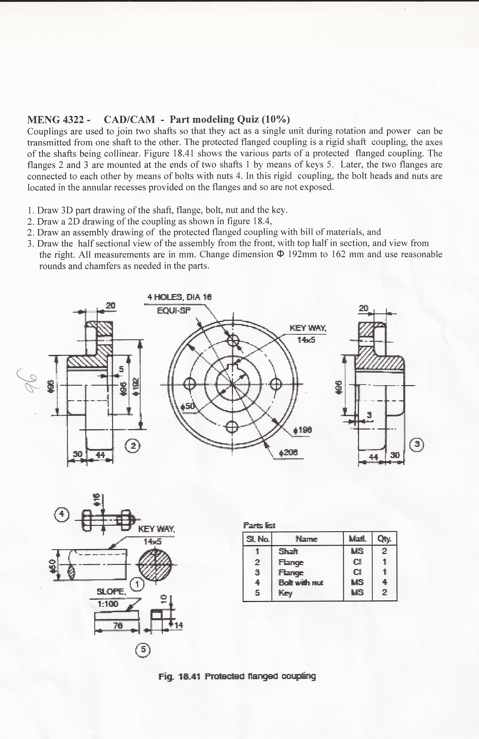
Solved Couplings Are Used To Join Two Shafts So That They Chegg Com

Anuniverse 22 Notes Md I Coupling 6 Design Of Flange Coupling Youtube

Detail Drawing Of Coupling Download Scientific Diagram
2 D Flange Coupling Model Download Scientific Diagram

Flange Coupling Eg Using Autocad Flange Coupling Assembly Drawing Step By Step Process Youtube

Flange Coupling In Autocad Youtube

Machine Drawing Flange Coupling
0 comments
Post a Comment