Start a timer that fires at time t error_t startTimerOneShottimer_handler_t handler uint32_t t. A delay is specified by a followed by the delay amount.

Delay Timer Ls7212 In Verilog Hdl Fpga4student Com
Input is the refresh clock created by clock divider module and outputs are all four digits on Basys 3.

. In this post we will design the AND logic gate using all the three modeling styles in Verilog. Luckily in the case of FPGA and Verilog we can use testbenches for testing Verilog source code. Initial r_value 0.
Minutes minutes 1. Market Verilog as both a language and a simulator. Verilog Delays are normally used in three places 1 Testbench verilog where it is essential Example.
End Generate the reset initial begin reset 1b1. We have earlier seen how we have used delays when creating a testbench. Ifseconds 60 begin check for max value of sec.
Negative numbers are represented as 2s compliment numbers. Typedef struct timer timer_handler_t handler. A Countdown Timer.
The clock generator see Verilog Testing notes Example code. A counter using an FPGA style flip-flop initialisation. Can anyone here give me the verilog code for a simple timer which generates a continous stream of interrupt pulses at intervals determined by a parameter abd each pulse should last 4 clock cycles.
I made a single-cycle RISC CPU in Verilog and it works well on a real FPGA I have. One of these components is a programmable timer that has a prescaler and counter and has multiple ways of counting time. Display 0t SIG Have CK-Q of d nstimesig_ck2o.
One-shot OS Delayed Operate DO Delayed Release DR Dual Delay DD. The specification of the delay timer can be easily found here. Learn verilog - Simple counter.
That is using Gate Level Dataflow and Behavioral modeling. Sig_ck2o sig_time - clk_time. 10 reset 1b0.
If you want to check the ck-out of output signal name sig you can do something like. This was a powerful combination. The clock system input Im using is 50 MHz.
To time input signals Example. Forever 1 clk clk. Verilog - Operators Arithmetic Operators cont I Unary operators I Operators and - can act as unary operators I They indicate the sign of an operand ie -4 negative four 5 positive five.
Use the following timescale constructs to use different time units in the same design. Minutes 0. Edit save simulate synthesize SystemVerilog Verilog VHDL and other HDLs from your web browser.
Always posedge clk begin count. The verilog code below shows how the clock and the reset signals are generated in our testbench. It has multiple components that communicate over an internal bus.
Apr 8 2011 2 L. For example if with timescale 2ns100ps a delay with statement. Create the vector register variable pattern to have the initial pattern for digit.
Else if r_value 0 r_value. Verilog - creating a timer to count a second - EDA Playground Loading. Always posedge i_clk if i_start r_value.
Design a countdown timer using the behavioral modeling to model a parameterized counter down counter with the desired input control signals to show the count down time from a desired initial value set by the two slide switches of the board at a second resolution. Start a timer that fires every dt time interval error_t startTimerContinuoustimer_handler_t handler. Module counter input clk output reg70 count initial count 0.
Basically the delay timer has 4 operating modes. Remember the digit is active low logic refer to the How to use Verilog and Basys 3 to do 3 bit counter instructable project. This counter starts at zero.
Else ifClk_1sec 1b1 begin at the beginning of each second. Seconds seconds 1. Verilog It can be simulated but it will have nothing to do with hardware ie.
For example if the frequency of the clock is set to 640000 kHz then its clock period will be 15625 ns for which a timescale precision of. Hence it is essential to verify any design before finalizing it. The equation I used to determine N was 150000000 2N 1 which gave.
I got most of it done but it lasting for 4 clock cycles i dont know how to do. Hence it is important that the precision of timescale is good enough to represent a clock period. Notice the different approaches in the different styles to get the same end result an AND gate.
Simulations are required to operate on a given timescale that has a limited precision as specified by the timescale directive. Verilog code for the delay timer is fully presented. It works fine and can generate PWM output verified.
Store the time and make your own calculation. Timescale time_precision Example timescale 1 ns 1 ps timescale 10 us 100 ns timescale 10 ns 1 ns. Verilog cannot match operands multiple constant drivers 1 answer Closed 5 years ago.
Example testbench to generate input signals always begin reset 1b1. Integer clk_time sig_time sig_ck2o. Timing Control and delays in Verilog.
Im using a FPGA BEMICROMAX10 to create a digital clock using seven segment displays on a breadboard and Im having issues getting the seconds to count exactly 1 second. The exact duration of the delay depends upon timescale. It is ineffective in terms of time money and resources.
Im using a FPGA BEMICROMAX10 to create a digital clock using seven segment displays on a breadboard and Im having issues getting the seconds to count exactly 1 second. In 1990 Cadence recognized that if Verilog remained a closed language the pressures of standardization would eventually cause the industry to shift to VHDL. Display the time in MMSS format on the three 7-segment displays.
Any time an i_start signal takes place the counter is set to TIMEOUT and then counts down to zero as illustrated in Fig 2. Im going to post just the relevant code to the seconds. We dont spend much time on Behavioral Verilog because it is not a particularly good language and isnt useful for hardware synthesis.
Generate the clock initial begin clk 1b0. Always posedge clk clk_time time. Always sig begin sig_time time.
In this article we will learn how we can use Verilog to implement a testbench to check for errors or inefficiencies. The digital delay timer being implemented is CMOS IC LS7212 which is to generate programmable delays. At the same time Synopsys was marketing the topdown design methodology using Verilog.
Initialize the virtual timer void initTimer. Will mean a delay of 100 ns. Ifminutes 60 begin check for max value of min.
The time_unit is the measurement of delays and simulation time while the time_precision specifies how delay values are rounded before being used in simulation.
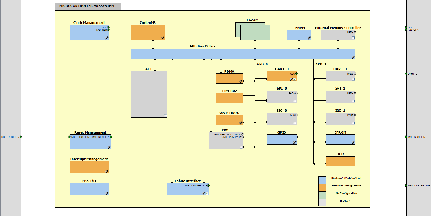
Eecs 373 Lab 5 Clocks Timers And Counters

Delay Timer Ls7212 In Verilog Hdl Fpga4student Com
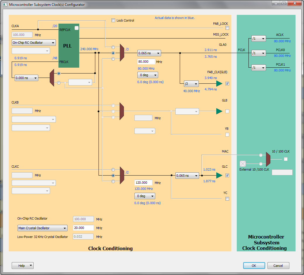
Eecs 373 Lab 5 Clocks Timers And Counters

Verilog Code For Clock Divider On Fpga Fpga4student Com
How To Create A Timer In Vhdl Youtube
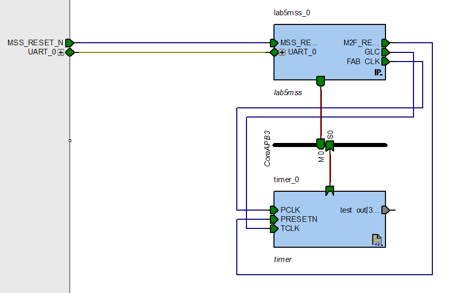
Eecs 373 Lab 5 Clocks Timers And Counters
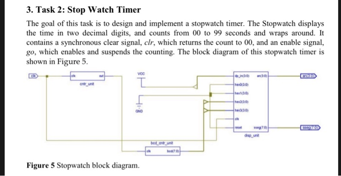
Create The Verilog Source File S For A Stopwatch Chegg Com

Ziptimer A Simple Countdown Timer
0 comments
Post a Comment